LINO Touch MAX Intelligent Poultry Environmental Controller
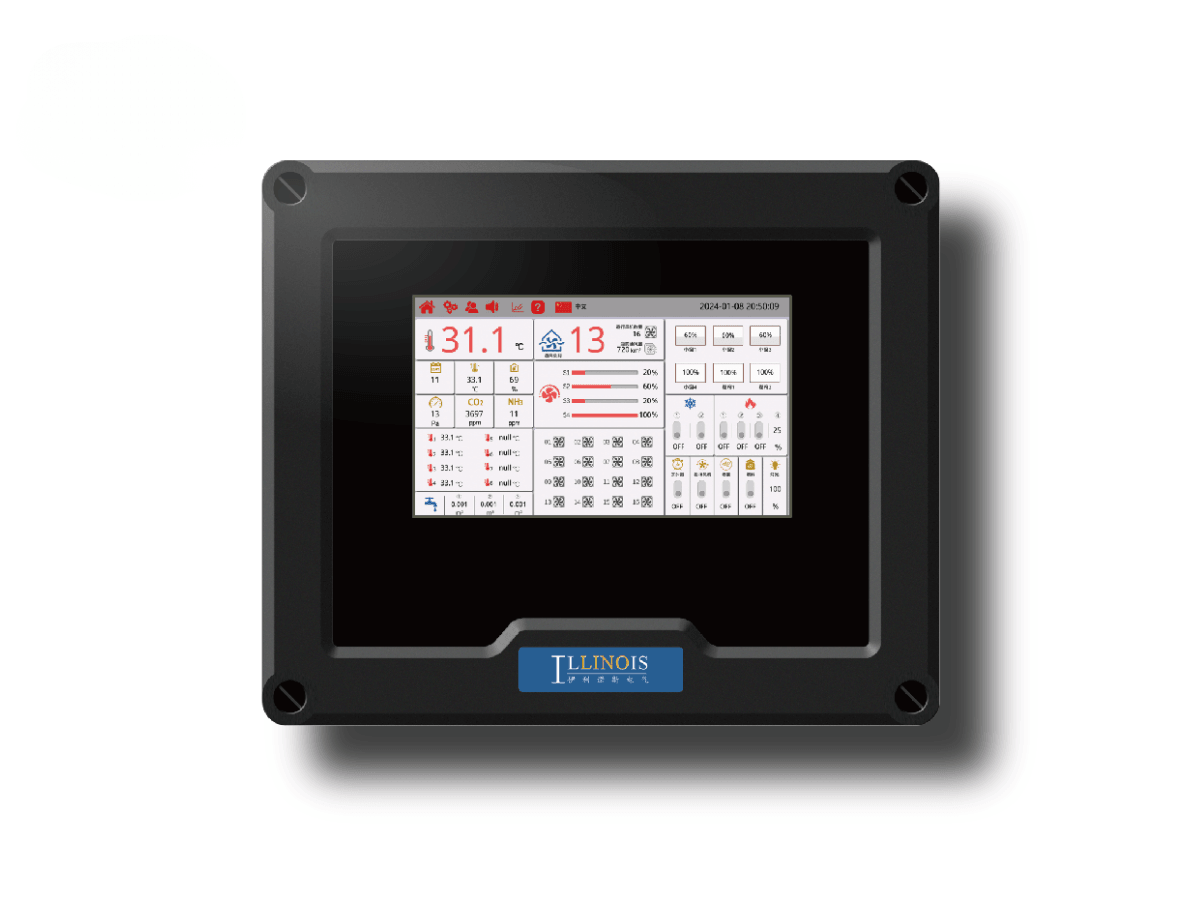
LINO Touch MAX is a 10-inch poultry environmental controller for standardized daily operation in modern poultry houses. It supports four variable-speed control channels, 16 fixed-speed fan groups, 30 ventilation stages, six air-inlet groups, three heating zones and relay expansion up to 36 outputs. Expansion hardware and communication must be confirmed against the final equipment list.
Product description
A 10-Inch Operating Center for Standard Poultry-House Control
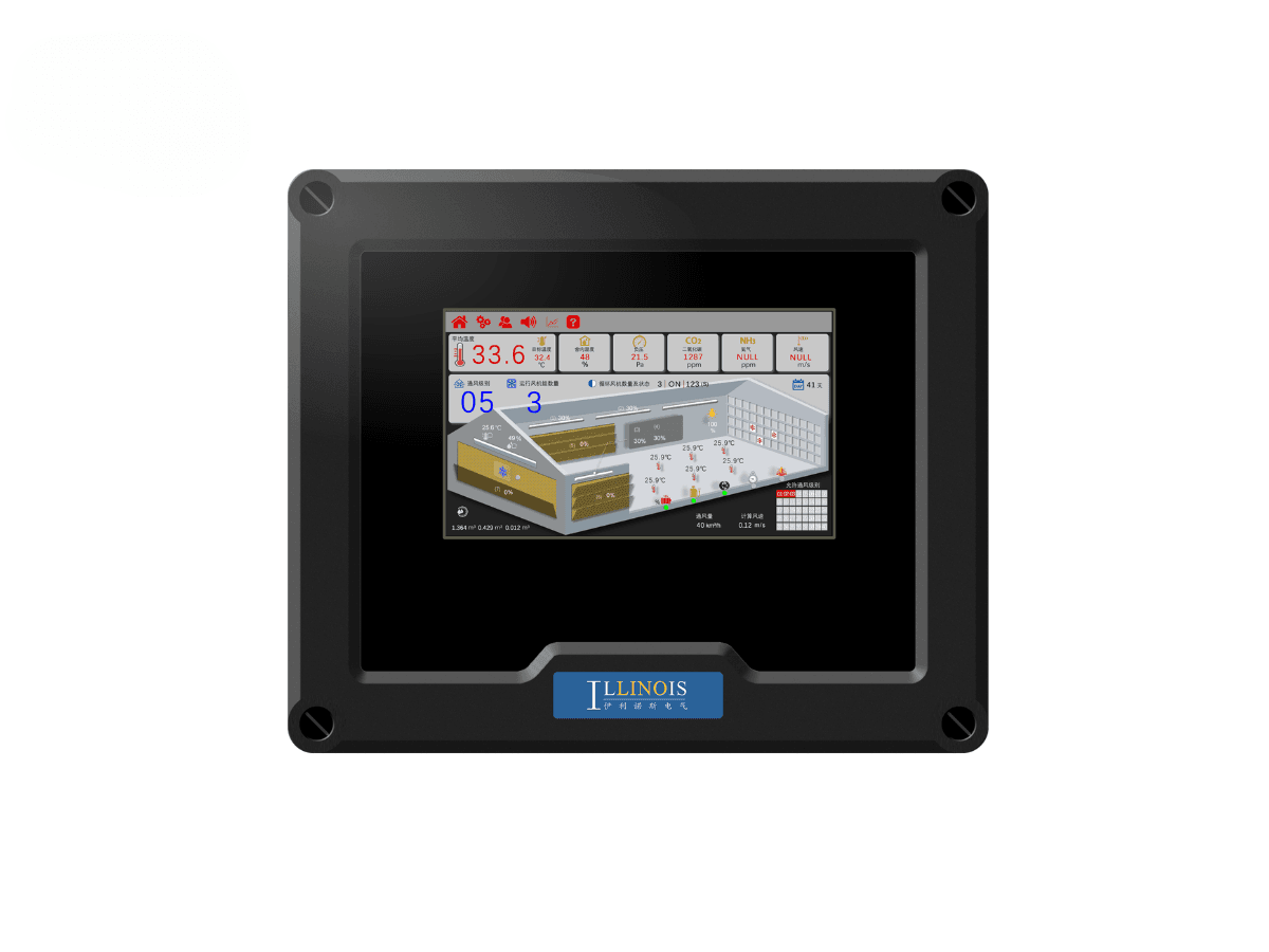
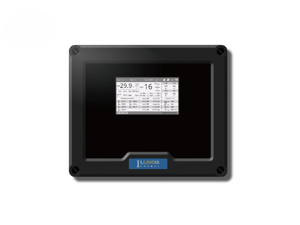
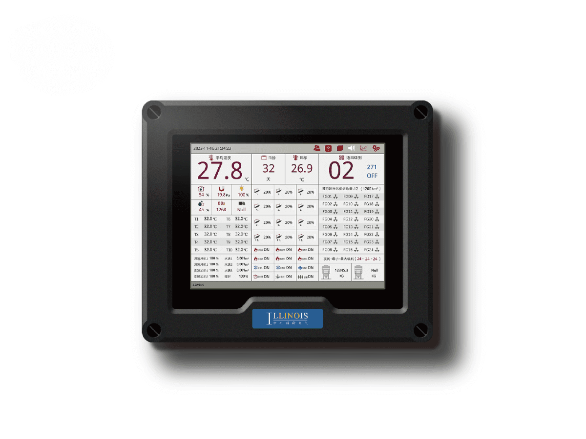
LINO Touch MAX is positioned as an operator-centered control platform for poultry houses that need a clearly defined but expandable control scope. Its 10-inch touchscreen brings the main environmental readings, ventilation status and assigned equipment functions into one local interface.
The MAX is a standardized daily operating center. It is not the highest-capacity LN-9900 architecture, the project-customizable Pro+ engineering platform or the fixed 15-relay SE+ controller. The value of MAX is the ability to organize a repeatable house-control routine around a known set of fan groups, ventilation stages, air inlets and auxiliary functions.
What Operators See on the Main Dashboard
The touchscreen can present current environmental values, assigned equipment status and alarm information in one operating view. Depending on the selected sensors, operators may review temperature, humidity, CO2, NH3 and negative-pressure information together with the status of fan groups, air inlets, heating and other connected functions.
The purpose of the dashboard is operational clarity. It should help the farm team confirm what the controller is reading, which stage is active and whether an alarm or equipment condition requires attention.
Turning Sensor Readings into a 30-Stage Ventilation Routine
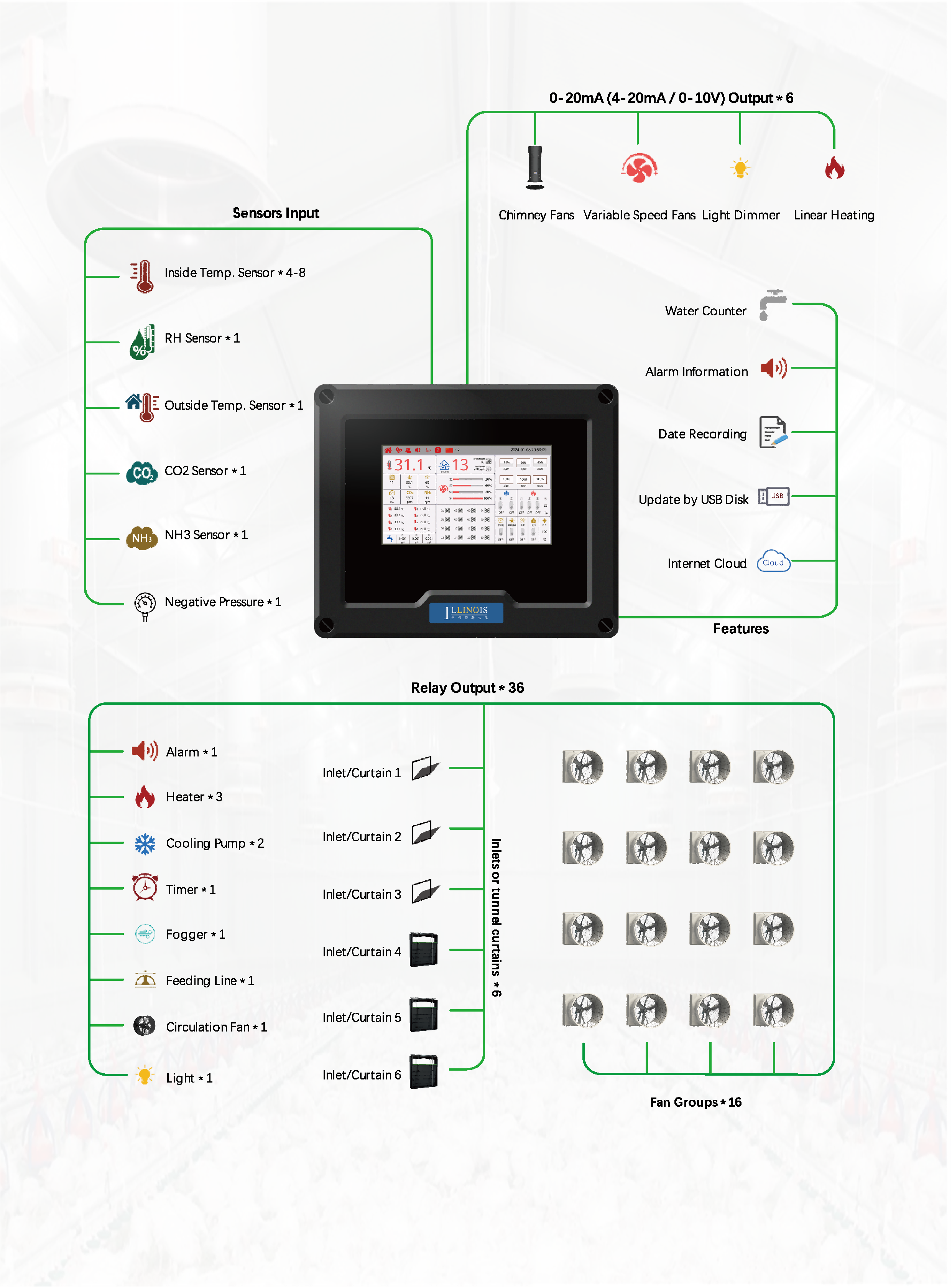
MAX supports up to 30 ventilation stages. These stages provide a structured sequence for changing ventilation output as environmental demand changes. Four variable-speed control channels can be used for proportional adjustment, while fixed-speed fan groups can be added in stages as the required airflow increases.
The 30 stages are a programming framework, not 30 independent controllers or guaranteed energy-saving modes. The final sequence must be designed around the installed fans, motor-control hardware, inlet arrangement and poultry-house ventilation plan.
Managing 16 Fixed-Speed Fan Groups with Clear Operating Status
The current MAX configuration supports up to 16 fixed-speed fan groups. A fan group may contain one or more fans assigned to the same control stage, so the capacity is described as fan groups rather than 16 individual fans.
For daily operation, the equipment list should give every group a clear name and stage position. This makes it easier for operators to compare the active ventilation stage with the actual fan status and to identify a group that does not respond as expected.
Coordinating Six Air-Inlet Groups with House Pressure
The controller can coordinate up to six air-inlet or curtain groups. Inlet movement should be programmed together with the selected fan stages so that the ventilation sequence manages airflow entry and exhaust as one process.
Relay outputs can be used for open-and-close operation, while the current I/O information also shows proportional inlet-control options through an additional analog-output module. Actuator type, feedback signal and control range must be confirmed before the inlet function is described as proportional.
For broader design principles, farm planners can review our environmental control guide for layer chicken farming.
Three Heating Zones and Assigned Auxiliary Functions
The published MAX capacity includes up to three heating zones, two cooling-pump groups, one fogging function, one timer relay, one circulation-fan group and one light-brightness function. Relay and analog outputs may also be assigned to feeding or other approved auxiliary equipment according to the final control plan.
These capacities describe available control functions, not the electrical load that the controller can directly carry. Heaters, pumps, fans and other high-power equipment may require contactors, motor protection, drives or a separate electrical cabinet.
Building a Repeatable Relay Map for Daily Farm Operation
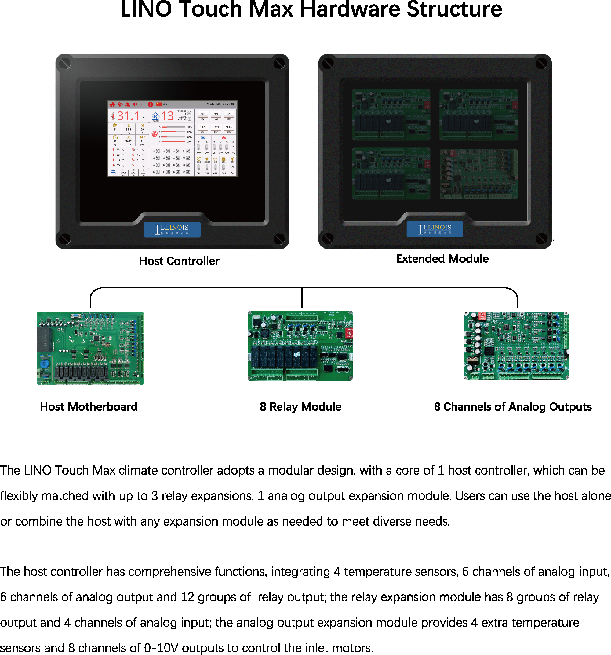
The host controller provides 12 relay outputs. One to three relay extension modules can add eight outputs per module, giving a published maximum of 36 relay outputs.
For MAX, the key task is not unlimited customization. It is creating a repeatable relay map for the house: which outputs operate fan groups, which operate air inlets, which are reserved for heating or cooling, and which support alarms or auxiliary equipment. A documented relay map helps commissioning, operator training and future troubleshooting.
Expansion modules must be selected from the actual equipment list and must not be presented as standard components included with every controller.
Using Water, Feed-Level and External Alarm Inputs
The current I/O information includes digital inputs for a water counter, a feeding-level signal and a custom external alarm input. These inputs allow selected farm signals to be displayed or included in the approved control logic.
MAX can receive selected water-counter, feed-level and external alarm signals, while dedicated feed-silo weighing and poultry-weighing systems are still required for accurate inventory and bird-growth management. Its role is to coordinate these signals with the environmental-control workflow when the required external equipment and interfaces are included.
Alarm Review, Data Records and Shift Handover
Alarm information and operating records can support a more consistent handover between farm shifts. The outgoing operator can review abnormal conditions, active alarms and recent controller status before the next operator takes responsibility for the house.
This is an operating-management benefit, not automatic fault diagnosis or a guarantee of preventing equipment failure. Alarm thresholds, record capacity, retention period and notification method must be confirmed for the selected configuration.
USB Updates and PC or Smartphone Access
The current product information lists system updates by USB flash drive together with PC and smartphone communication. These functions should remain configuration-dependent because the network hardware, software platform and available remote actions are not identified in the public materials.
Before ordering, the buyer should state whether the project requires local PC viewing, remote monitoring, alarm access or another communication arrangement so that the required hardware and software can be confirmed.
Main Control Capacity
| Item | Capacity |
|---|---|
| Touchscreen | 10 inches |
| Variable-speed control channels | Up to 4 |
| Fixed-speed fan groups | Up to 16 |
| Ventilation stages | Up to 30 |
| Air inlets or curtains | Up to 6 groups |
| Heating zones | Up to 3 |
| Cooling-pump groups | Up to 2 |
| Fogging system | 1 |
| Timer relay | 1 |
| Circulation-fan group | 1 |
| Light-brightness function | 1 |
| Host relay outputs | 12 |
| Maximum relay outputs | Up to 36 |
| Temperature inputs | Up to 8 |
| Humidity / CO2 / NH3 / negative-pressure inputs | Supported according to configured analog inputs |
| System update | USB flash drive |
| PC and smartphone communication | Available according to configuration |
Controller I/O and Expansion Options
| Component | Quantity | Published Inputs / Outputs | Intended Use |
|---|---|---|---|
| Host controller | 1 set | 4 temperature inputs | Local temperature monitoring points |
| Host controller | 1 set | 6 analog input channels | Humidity, CO2, NH3, negative-pressure and inlet-feedback signals |
| Host controller | 1 set | 4 digital input channels | Water counter, feed-level signal and custom external alarm input |
| Host controller | 1 set | 6 analog output channels | Compatible variable-speed fans, dampers, light-brightness or heating control according to signal configuration |
| Host controller | 1 set | 12 relay outputs | Fan groups, air inlets, heating, cooling pumps, fogger, timer, feeder, circulation fan, lighting and alarm according to relay map |
| Relay extension module | 1-3 pieces | 8 relay outputs per module | Additional fixed-speed fan groups and air-inlet or curtain functions |
| Relay extension module | 1-3 pieces | 4 analog input channels per module | Air-inlet position feedback where supported |
| Analog output module | 1 piece | 8 analog output channels | 0-10V control for compatible inlet actuators |
| Temperature extension | 1 piece | 4 additional temperature inputs | Additional temperature points subject to technical confirmation |
Climate and Feeding Coordination in a Malaysia Poultry Project
A Malaysia poultry automation project used the LINO Touch MAX poultry climate controller to monitor temperature, humidity and ammonia and to support coordination between environmental conditions and the feeding schedule.
The project shows MAX inside an integrated operating process rather than as an isolated touchscreen. The statement is limited to facts published in the case. Feed-waste reduction, labour savings and other project results must not be presented as guaranteed controller performance.
Where LINO Touch MAX Fits in the Controller Range
MAX is the 10-inch standard-capacity controller for a defined commercial poultry-house configuration. LN-9900 is the higher-capacity multi-zone platform, Pro+ is the relay-expandable project and OEM platform, and SE+ is a compact fixed-capacity controller.
This section helps buyers compare control scope, not declare one model universally better. Selection depends on the required fan groups, ventilation stages, air inlets, relay budget, sensors and integration needs.
Information Needed to Build a Standard MAX Configuration
Before preparing a MAX configuration, the buyer should provide:
- poultry-house layout and equipment locations;
- variable-speed channels and fixed-speed fan groups;
- required ventilation stages;
- air-inlet or curtain groups and actuator type;
- required environmental sensors;
- heating zones, cooling pumps, fogging, timer, lighting and circulation-fan functions;
- water-counter, feed-level and external alarm requirements;
- local voltage, electrical drawings and external protection devices;
- PC or smartphone communication requirements.
This information is used to confirm the relay map, expansion modules and final control sequence.
Related Guidance for Climate and Feed Management
For a broader explanation of how environmental conditions affect feeding and feed use, see our feed and climate control guide for poultry farms.
This guide provides a broader operational reference for coordinating feed use and environmental conditions. MAX itself does not replace dedicated silo-weighing, bird-weighing or complete feeding-management systems.
Frequently Asked Questions
What is the main role of the LINO Touch MAX in a poultry house?
It serves as a 10-inch operating center for a defined poultry-house control configuration. Operators can review environmental readings, ventilation status, assigned equipment functions and alarms from one interface.
How do the 30 ventilation stages work?
The stages provide a programmed sequence for changing ventilation output. Four variable-speed control channels can make proportional adjustments, while fixed-speed fan groups can be added as demand increases. The final sequence must match the installed ventilation system.
Does support for 16 fan groups mean 16 individual fans?
No. A fan group is a control group and may contain one or more fans assigned to the same stage. The final group arrangement depends on the electrical and ventilation design.
How are the six air-inlet groups coordinated?
The inlet groups should be programmed with the fan stages so that air entry and exhaust respond as one ventilation sequence. Actuator type, feedback and proportional control must be confirmed for the project.
How can the controller reach up to 36 relay outputs?
The host provides 12 relay outputs. One to three optional relay modules can add eight outputs each. The modules are selected from the equipment list and are not automatically included with every controller.
Can MAX receive water-counter and feed-level signals?
The current I/O information includes digital inputs for a water counter, a feed-level signal and a custom external alarm. MAX can receive selected signals, but it is not a substitute for a dedicated silo-weighing or poultry-weighing system.
How do alarm records support daily operation?
Alarm information and operating records can help operators review abnormal conditions and improve shift handover. Record capacity, retention period and notification methods must be confirmed for the selected configuration.
How many temperature inputs are available?
The current configuration supports up to eight temperature inputs. The final sensor arrangement should follow the approved technical specification for the project.
How was LINO Touch MAX used in the Malaysia project?
The project page states that MAX monitored temperature, humidity and ammonia and supported coordination between the poultry-house environment and the feeding schedule. Project results are not guaranteed outcomes for every installation.
What information is required before ordering a MAX controller?
Provide the house layout, fan groups, variable-speed channels, ventilation stages, inlet groups, sensors, heating and cooling functions, auxiliary equipment, electrical drawings and required PC or smartphone communication.
For right-sized automation lessons from a medium-sized Ontario layer farm, see our field visit note.
Compare MAX with SE+, Pro+ and LN-9900 in our controller selection guide.