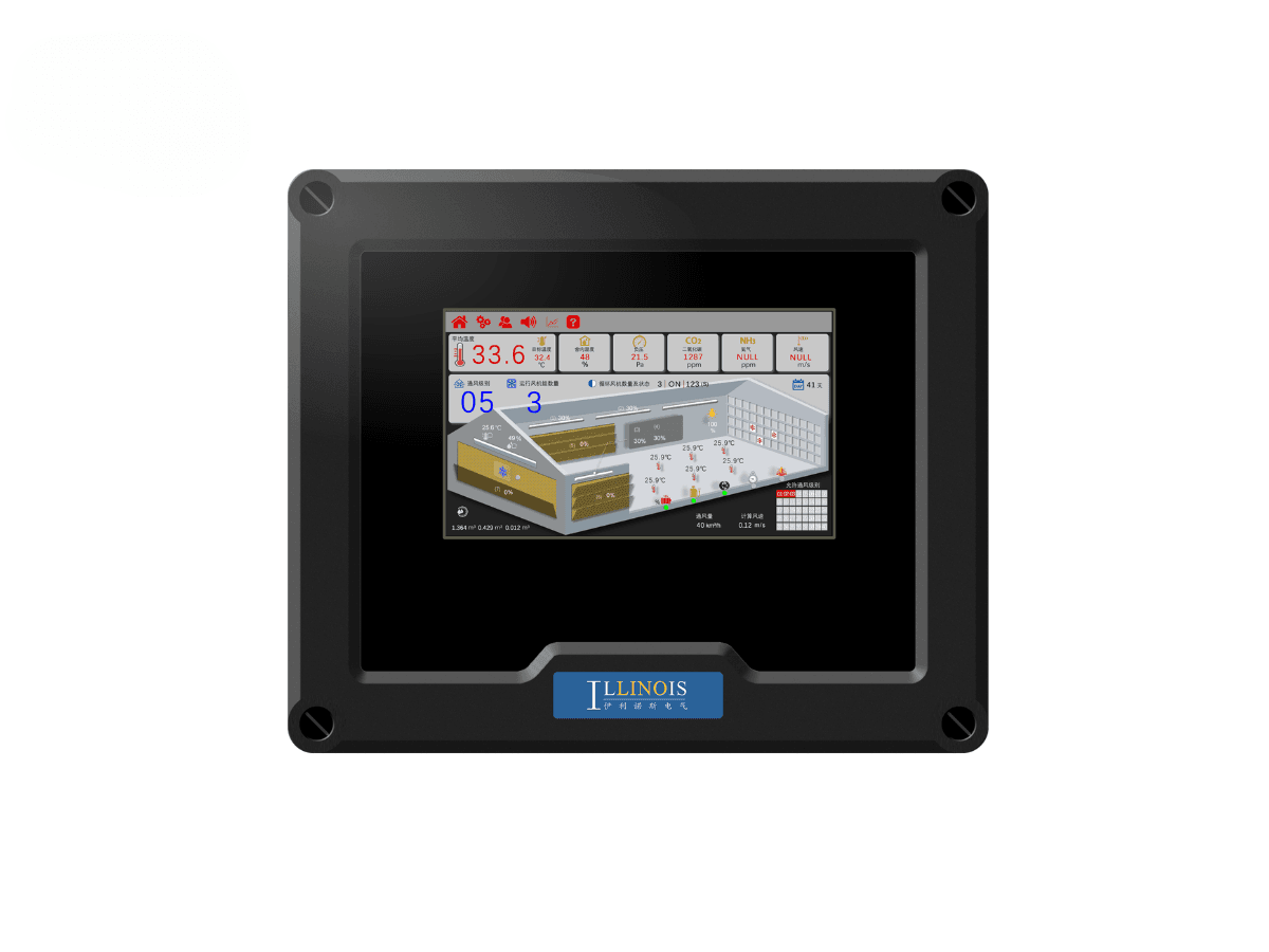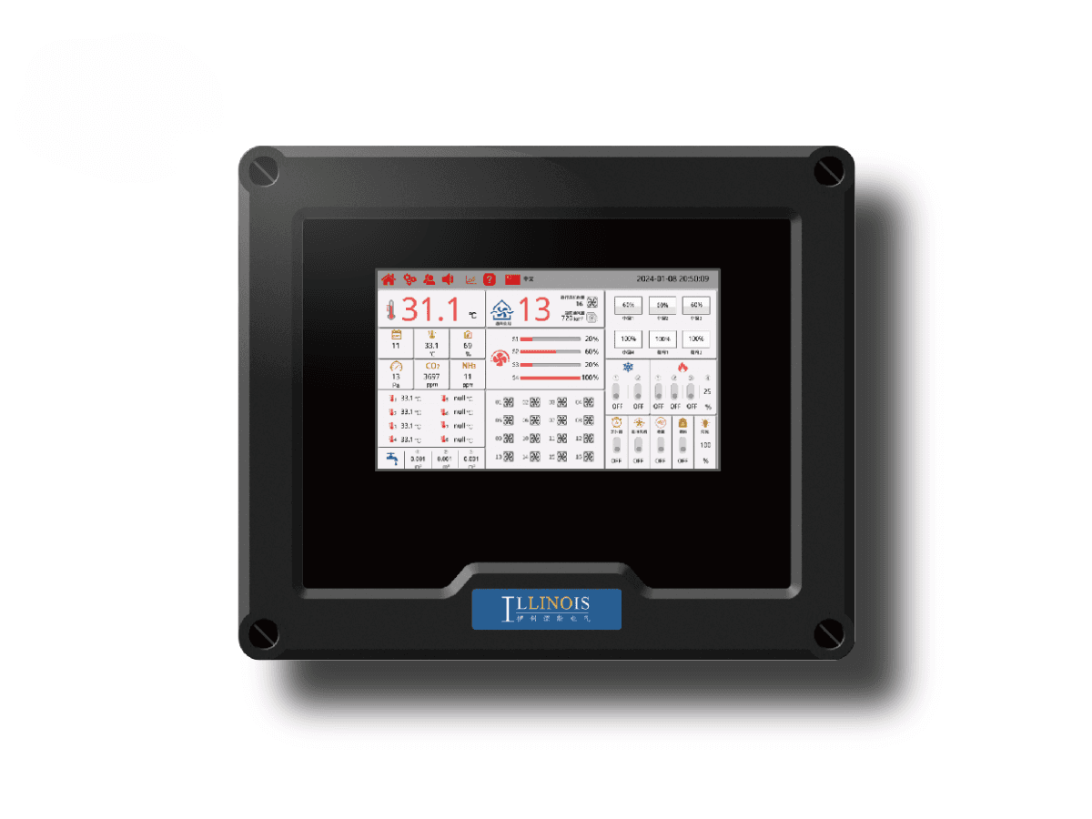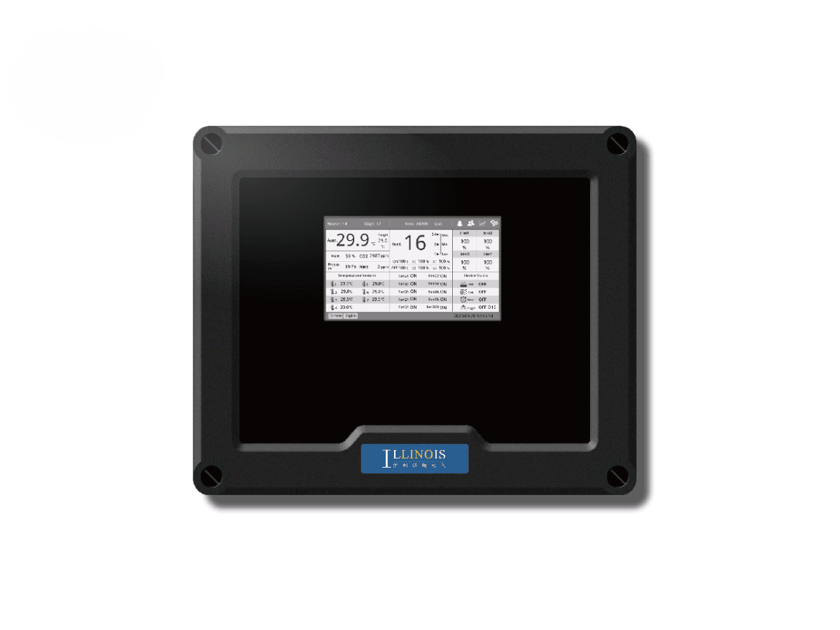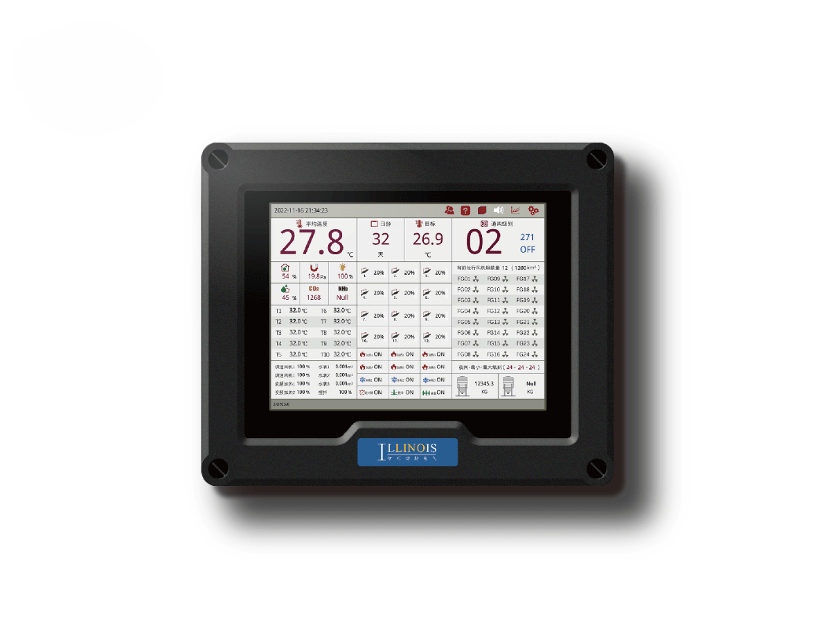
LINO Touch Pro+ Modular Poultry Environmental Controller
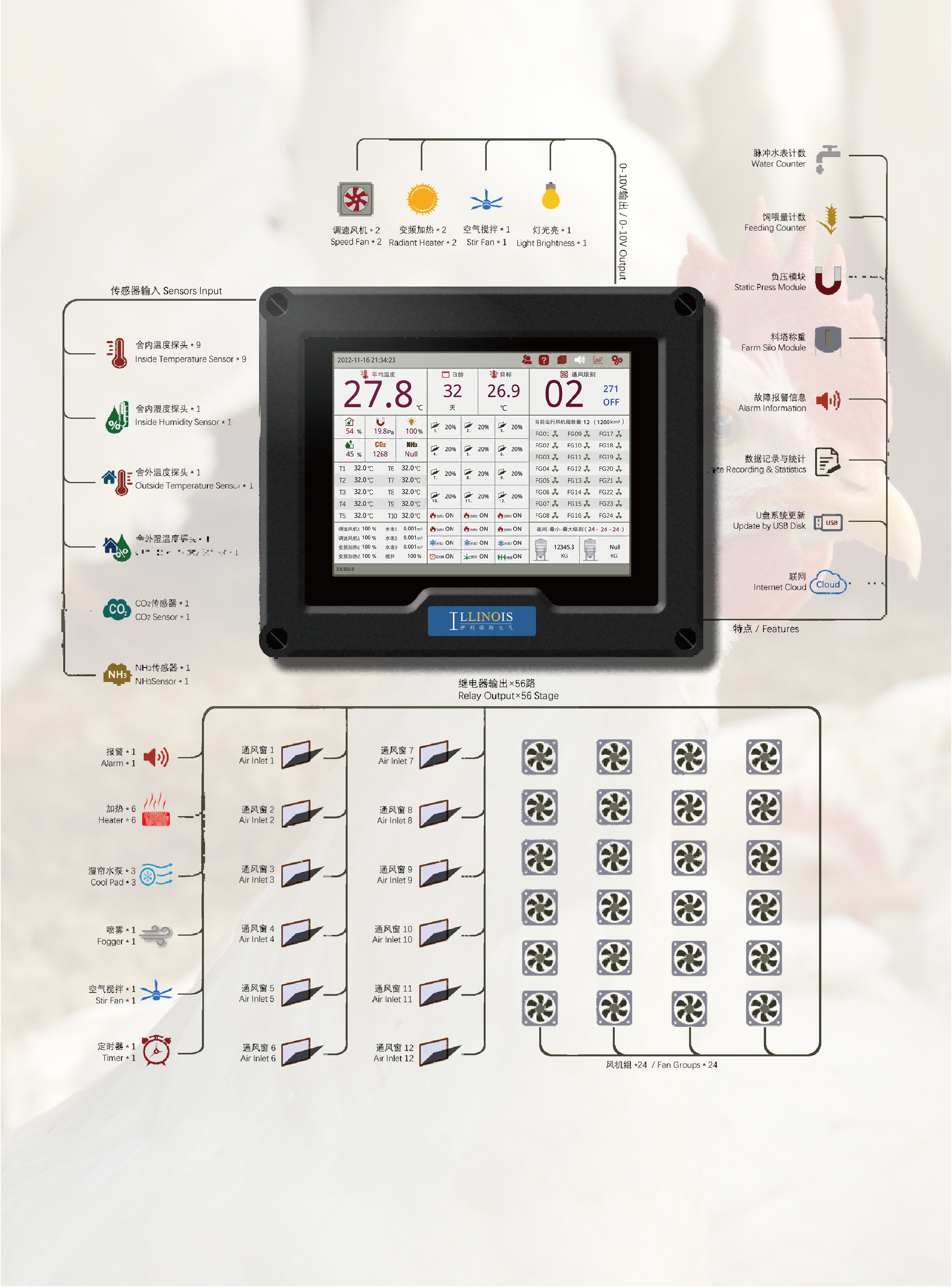
LINO Touch Pro+ is a 10-inch modular poultry environmental controller developed for projects that require a configurable relay map and a wider equipment-control scope. The current platform supports up to 56 relay outputs, 24 fixed-speed fan groups, 30 ventilation stages, 12 air-inlet or curtain groups, six relay-controlled heating groups and two additional heating-control channels, with OEM/ODM configuration available.
Product description
A Project-Configured Controller for Complex Poultry Houses
LINO Touch Pro+ is designed for poultry projects that cannot be defined by a small fixed relay map. Its 10-inch touchscreen and expandable relay platform allow the control system to be configured around an approved equipment list, operating sequence and electrical design.
The platform is intended for projects where fan groups, air inlets, heaters, cooling equipment, alarms and auxiliary functions must be assigned to a project-specific control matrix. This engineering-led positioning separates Pro+ from standardized or fixed-capacity controller models.
Build the Equipment List and Control Matrix First
A Pro+ configuration begins with a complete equipment list and control matrix. The list should identify every fan group, air-inlet or curtain group, heater, cooling pump, fogging function, timer, circulation fan, counter, alarm and approved auxiliary output.
For each item, the project team defines the required control method, relay or proportional output, feedback requirement, operating stage and external electrical component. The approved matrix then guides relay allocation, software logic, electrical-panel design, testing and commissioning.
Expandable Relay Capacity for Project-Specific Control
The Pro+ platform can be expanded to up to 56 relay outputs. This figure represents the maximum project relay capacity rather than the number of devices supplied or connected as standard.
The final relay count is calculated from the approved control matrix. External contactors, motor-protection devices, drives and control panels may still be required because relay quantity does not define the electrical load that the controller can directly switch.
Configurable Relay Assignment for Different Farm Functions
Relay functions can be assigned according to the approved project requirements. Fan groups, air inlets, heating, cooling, fogging, timers, circulation fans and alarms can be mapped to the available relay plan after the control logic has been reviewed.
Each assigned function uses part of the available capacity and must match the software version and electrical drawing. Changes requested after production may require program revision, wiring changes or additional hardware.
Coordinate 24 Fan Groups Across 30 Ventilation Stages
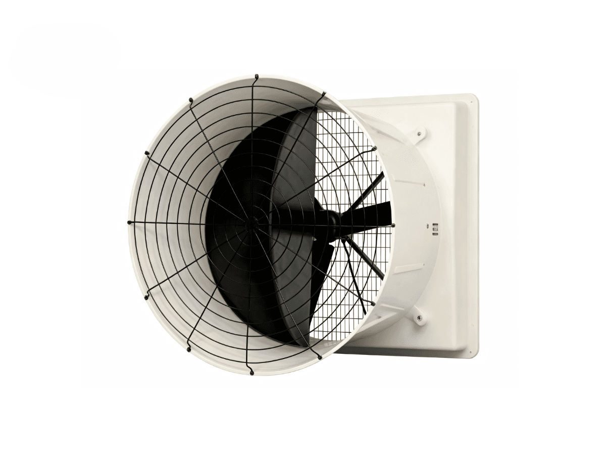
Pro+ supports up to 24 fixed-speed fan groups and up to 30 ventilation stages. Two variable-speed fan control channels are also shown in the current product architecture.
The ventilation design defines which groups operate during minimum, transitional and higher-output stages, and how variable-speed channels are used before or between fixed-group changes. Fan-group sequencing must be matched to the installed fans, poultry-house airflow demand and electrical design.
For the underlying calculation and equipment-selection process, review our poultry house ventilation design and equipment selection guide.
Plan Up to 12 Air-Inlet or Curtain Groups
Pro+ supports up to 12 air-inlet or curtain groups. The project specification should define which inlet groups move with each ventilation stage and how their actuators are controlled.
Actuator type, open-and-close logic, proportional control requirements and position feedback should be confirmed before production. These details determine the required control interface and electrical design.
Integrate Environmental Sensors, Counters and Farm Modules
A project configuration can include up to ten temperature sensors, two humidity sensors, one CO2 input, one NH3 input and one static- or negative-pressure input. Water-counter, feeding-counter and farm-silo-module signals can also be incorporated when compatible equipment and software functions are specified.
Supported signals are selected according to the project. Sensor models, input types, monitoring points, calibration requirements and data functions should be confirmed before production.
Configure Heating, Cooling and Auxiliary Equipment
The published project capacity includes up to six relay-controlled heating groups, three cooling-pump groups, one fogging system, one timer and one circulation or stir-fan function. Two additional heating-control channels are also available.
The equipment type, electrical load, external contactors, interlocks and signal type for the additional heating-control channels are defined during technical configuration. The controller output plan must be coordinated with the project electrical drawings.
Alarm Records, USB Updates and Optional Network Access
Pro+ can display alarm information and support operating records and statistics for configured functions. System updates can be completed through a USB flash drive.
PC, smartphone and internet access are available according to the selected configuration. Network hardware, communication method, user permissions, remote actions and software scope should be confirmed in the project specification.
OEM and ODM Configuration Workflow
OEM and project-specific Pro+ configurations can follow a controlled engineering workflow:
- Collect the equipment list and operating sequence;
- Prepare the I/O and relay matrix;
- Confirm screen pages, alarm logic and user functions;
- Review the electrical drawing and external control hardware;
- Build and test the approved prototype;
- Record the final software and hardware version before batch production.
This process helps align the controller, software and electrical system with the approved project scope.
Main Project Capacity
| Item | Capacity |
|---|---|
| Touchscreen | 10 inches |
| Maximum relay outputs | Up to 56 |
| Temperature sensors | Up to 10 |
| Humidity sensors | Up to 2 |
| CO2 input | 1 supported input |
| NH3 input | 1 supported input |
| Static / negative-pressure input | 1 supported input |
| Variable-speed fan control channels | Up to 2 |
| Fixed-speed fan groups | Up to 24 |
| Ventilation stages | Up to 30 |
| Air inlets or curtains | Up to 12 groups |
| Relay-controlled heating groups | Up to 6 |
| Additional heating-control channels | 2; signal type to be confirmed |
| Cooling-pump groups | Up to 3 |
| Fogging system | 1 |
| Timer function | 1 |
| Circulation / stir-fan function | 1 |
| Light-brightness function | 1 |
| Water counter / feeding counter / farm silo module | Supported according to configuration |
| Alarm, recording and statistics | Supported |
| System update | USB flash drive |
| PC / smartphone / internet capability | Available according to configuration |
Project Configuration Matrix
| Controlled Function | Published Capacity / Support | Project Decision Required |
|---|---|---|
| Fixed-speed ventilation | Up to 24 fan groups | Group composition, stage order, electrical panel and protection. Fan groups are not individual fans. |
| Variable-speed ventilation | Up to 2 control channels | Motor/drive type, signal, minimum and maximum output. Signal type and motor compatibility to be confirmed. |
| Ventilation sequence | Up to 30 stages | Stage trigger, fan groups, inlet groups and alarms. No guaranteed airflow or energy result. |
| Air-inlet / curtain control | Up to 12 groups | Actuator type, relay/proportional method and feedback requirement. Feedback and 0-10V are not confirmed. |
| Heating | 6 relay groups + 2 additional control channels | Equipment type, load, signal and external contactors. Additional-channel terminology requires confirmation. |
| Cooling / fogging / circulation | 3 cooling pumps, 1 fogger, 1 circulation/stir fan | Equipment load, interlock and protection. |
| Environmental sensors | 10 temperature, 2 humidity, CO2, NH3 and pressure inputs shown | Sensor model, signal, location and calibration plan. Supported does not mean included. |
| Counters and farm modules | Water counter, feeding counter and farm silo module shown | Compatible device, data scope and software logic. Independent weighing/feeding management is not claimed. |
| Alarm and records | Supported | Thresholds, priorities, record scope and notification method. |
| Communication | PC/smartphone/internet capability shown | Network, software, protocol, user access and remote actions. Configuration dependent. |
Confirm the Final Specification Before Production
Before production, the approved documentation should confirm the final relay count, fan groups, ventilation stages, inlet groups, sensor package, heating and cooling outputs, counters, farm modules, alarm logic, communication scope and external electrical hardware.
The production version should be tied to an approved control matrix, electrical drawing and software version so that the delivered controller matches the agreed equipment sequence.
OEM/ODM Capability Reference
For projects requiring a customized interface, relay map, software logic or batch-production workflow, our custom climate controller OEM/ODM capability case provides a related development reference.
The case concerns a customized controller platform comparable to Pro+, rather than a standard off-the-shelf Pro+ installation. Product specification, customer authorization and public-use scope should remain separate from the standard Pro+ page.
Environmental-Control Guidance for System Planning
For the environmental principles behind the control matrix, continue with our environmental control guide for layer chicken farming.
The guide provides management context for temperature, humidity, ventilation and air quality. The final Pro+ capacity and compatible equipment remain defined by the product specification and project matrix.
RFQ Information for a Pro+ Control Project
A Pro+ RFQ should include:
- Poultry-house layout and complete equipment list;
- Fixed-speed and variable-speed fan groups;
- Required ventilation stages;
- Inlet or curtain groups and actuator method;
- Sensor types and monitoring points;
- Heating, cooling, fogging, timer and circulation functions;
- Water, feeding and silo-module requirements;
- Relay allocation and alarm priorities;
- Local voltage, electrical drawings and external protection devices;
- Required screen pages, language, communication and OEM scope.
This information allows the supplier to prepare a project control matrix and a traceable production specification.
Frequently Asked Questions
What type of project is LINO Touch Pro+ intended for?
It is intended for poultry projects that require a configurable relay map, a wider control scope and project-specific assignment of ventilation, inlet, heating, cooling, alarm and auxiliary functions.
How should a Pro+ configuration be started?
Begin with a complete equipment list and control matrix. The matrix identifies every controlled device, its control method, output requirement, feedback requirement, operating stage and external electrical hardware.
What does expansion to 56 relay outputs mean?
It is the maximum published project relay capacity. The final quantity depends on the approved equipment list and expansion design. It does not mean that 56 devices are included or that high-power equipment can be connected without contactors or protection.
Are the relay functions fixed?
Relay functions can be assigned according to the approved project requirements. The final assignments must match the controller software, electrical drawing and available capacity. Later changes may require program and wiring revisions.
How can 24 fan groups be used across 30 ventilation stages?
The project ventilation table defines which fan groups operate at each stage and how the two variable-speed channels are used between fixed-group changes. The sequence is based on the poultry-house ventilation design and installed equipment.
Can the controller manage 12 air-inlet groups?
Yes. Pro+ supports up to 12 air-inlet or curtain groups. The actuator type, control method and feedback requirement are confirmed in the project specification.
Which sensors and farm signals can be included?
A project configuration can include up to ten temperature sensors, two humidity sensors, CO2, NH3 and pressure monitoring, together with compatible water-counter, feeding-counter and farm-silo-module signals. Interface and data functions must be confirmed.
What are the two additional heating-control channels?
They provide project-specific heating-control capacity in addition to the six relay-controlled heating groups. The final signal type and compatible equipment are confirmed during technical configuration.
Does the OEM/ODM case represent a standard Pro+ installation?
No. It documents a customized controller development process and is included as a related OEM/ODM capability reference. The standard Pro+ specification is defined separately by the product page and approved project matrix.
What information is needed for a Pro+ RFQ?
Provide the equipment list, fan and inlet groups, ventilation stages, sensors, heating and cooling functions, counters and farm modules, relay priorities, electrical drawings, alarm logic, communication needs and required OEM scope.
See our poultry controller selection framework for modular projects.